400mW output with VOX Control from the PC audio.
Published in QST April 2017.
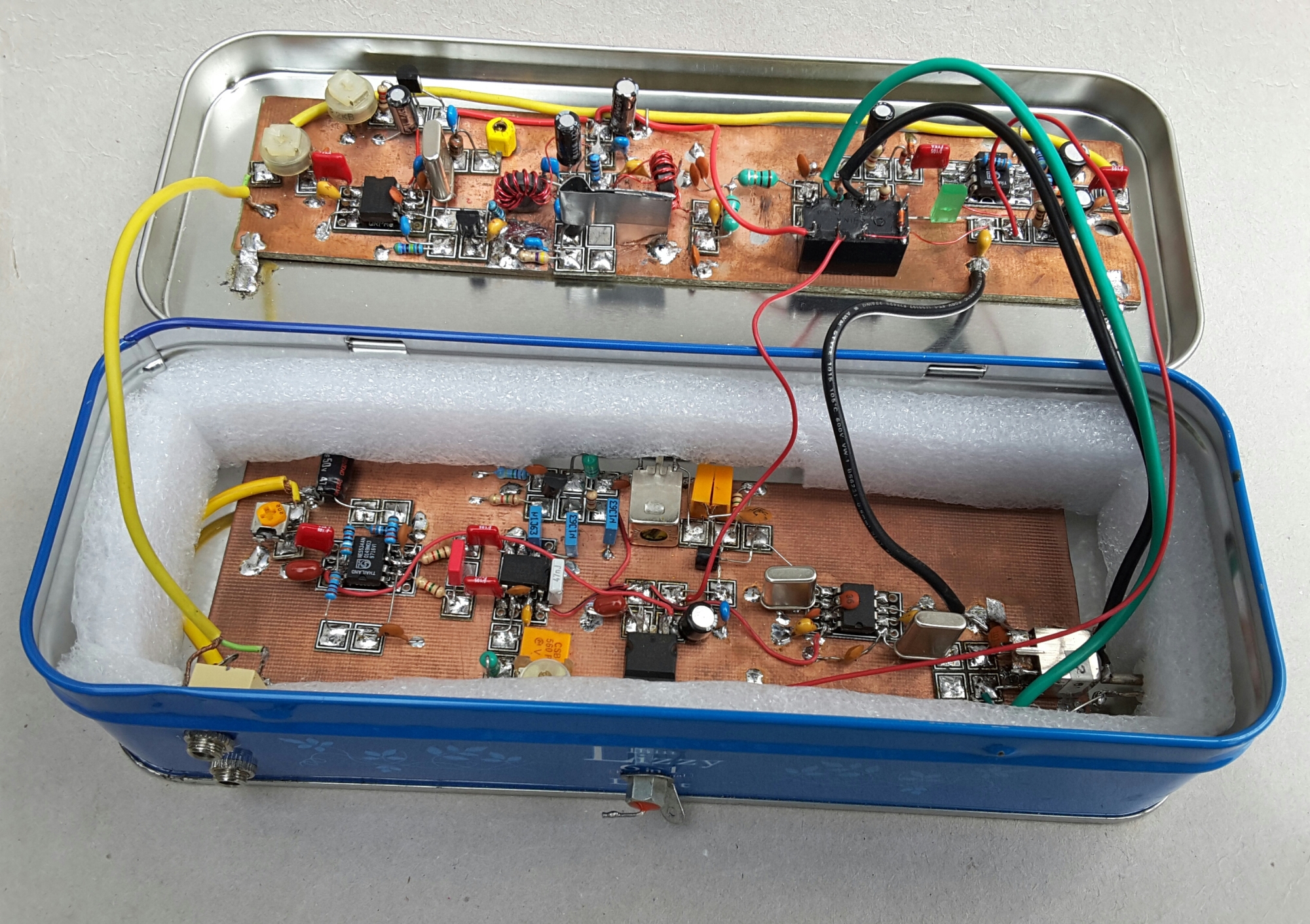
As shown in the heading pic, the transmitter will interface to the previously published receiver, via the changeover relay, which is VOX operated. The audio from the PC, or laptop, is buffered by the external USB sound-card. Since the computer does all the timing and data generation via the WSPR software, the only thing that needs to be taken care of is that the PC clock must be accurate. There are a number of applications available that will synchronise your PC clock to an atomic standard every time you start your system. Here is a good place to start http://www.worldtimeserver.com/atomic-clock/
This will ensure that your WSPR activities are within the standard 2 minute time slots. I recommend setting your transmission percentage to an odd value. This will tend to randomise your 2 minute listening and transmission slots over a period of time.

Voltage Regulator.
There doesn’t appear to be much merit in selecting a variable voltage regulator for this circuit. However, my initial design incorporated a FET PA which needed a bias voltage. Not having had much luck, or any experience, with the FET design, I resorted to a pretty standard bipolar circuit. Just set the output voltage to 8v before connecting the mixer supply Pin 8, to this supply node. The mixer device will surely destroy itself if you exceed 9v supply.
You can of course simply fit a fixed voltage regulator from the LM78xx 100mA range. Anything between and including 5v and 8v should work fine.
Audio Input and Mixer.
The WSPR audio input to the transmitter is controlled by the power slider control in the WSPR software. This control should be set to 75% to start with. I found the signal at the transmitter input, which is also connected to the VOX input, to be near 1V p-p. You may find a different level depending on your sound-card capability.
The preset pot at the mixer input should be set for 200-300mv on pin 1. If you can’t measure this voltage, set the pot to the ground end. Later, during the transmit cycle, adjust the pot until the signal can be seen in Spectran, or heard on your receiver. With no audio there should be no output as there will be no sidebands. Increasing the signal to more than about 300mv will not improve the output power and may well lead to distortion.
The 1nF capacitor is insurance against any RF getting into the audio port of the mixer, along with the audio, and generating unwanted products in the output.
The audio arriving at the transmit mixer, is ‘mixed’ with the oscillator frequency. The oscillator frequency is determined by the crystal, and the other components at Pins 6 and 7. In this case it is 10.140MHz. The NE602 ( SA612 etc. ) data sheet shows the formulae for calculating the values. They are not too critical so I used the nearest preferred values. The addition of TC1 and L1, enables the frequency to be ‘pulled’ slightly, in order to put the transmitter exactly on the 1500Hz marker in Spectran. See Alignment section.
You can of course fit almost any crystal here and by changing the LPF components you will move the transmitter to another band. Replacing the crystal with a VFO or synthesiser will also make it multi-band, again depending on the LPF components. This would be a great opportunity to construct a versatile CW transmitter.
Driver.
The mixer output at Pin 5 produces the DSB signal that we will use. With 7.5v supplied to the mixer, the output pins carry in excess of 6v DC in my prototype, so a capacitor is used to couple the signal into the gate of the driver FET. There is no need to match the output of the mixer to the gate impedance of the FET, as we are trying to transfer maximum signal voltage not power. The source resistor provides some 2v of gate bias via its voltage drop, and is bypassed at RF in order to maximise the signal gain. You should find over 2v p-p at the drain.
The drain transformer is bifilar wound and is connected as a centre tapped transformer providing a 4:1 impedance transformation whilst feeding RF to the base of the output transistor. I experimented at length with the number of turns and various tapping points. There was little difference in the output, unless I chose ridiculous ratios. However, using a 22uH choke for the drain load and coupling with a capacitor reduced the output considerably. So I stayed with the bifilar solution.
Output Amplifier.
The PA is broadband and runs in class AB, biased by 680R and the 1n4001 diode. Not the best bias configuration, but more than capable at this power level. A ferrite bead on the base leg guards against possible VHF parasitics which destroyed a couple of earlier devices.
The output devices may be any of a number of common NPN types. My choice of 2N3904 was determined by the fact that there were at least 100 of them in my spares box, and I got through quite a number of them. I experimented with a couple of other transistors before I realised there was a spurious VHF problem. As previously mentioned a ferrite bead cured that. I tried various resistor values in the emitter circuit, and reached the conclusion that, in this configuration at least, 4R7 is a good compromise between power output and thermal protection. At 2R2 the transistor gets hot. At 10R and higher, the output power naturally reduces.
A small heatsink is recommended. I used a small piece of scrap tin plate formed around the transistor and soldered to the PCB. The whole heatsink assembly is about half the size of a postage stamp. It gets warm during a 2 minute transmit cycle. If your device runs too hot then increase the surface area of the heatsink. Or raise the value of the emitter resistor at the cost of a reduction in output power.
The PA collector load is a trifilar broadband transformer. The 9:1 ratio transforms the collector impedance hopefully a bit closer to 50R in order to match into the following Low Pass Filter. Again I tried a number of different ratios here, and also a bifilar transformer as in the driver stage. The trifilar configuration appears to offer the best performance.
The LPF at the output is essential for removing the unavoidable harmonics. This filter is of a standard design, I have selected the values in order to use off the shelf components. This means that the LPF impedance is not actually 50R, but it is fairly close. At 1uH the -3db corner frequency is 10.7 MHz, the response is 40db down at 21MHz.
If you roll your own, the toroids should be FT37-6 wound with 18 turns. The response now will be very slightly higher due to the fractionally lower inductance of ( theoretically ) 0. 97uH.
I believe there is a 5% manufacturing tolerance with these toroids so minor manipulation of the number of turns may be required. i.e. If the measured output is considerably lower than 12v p-p or 400mW, remove one turn and measure the output again. In the vast majority of cases there should be no problems here.
VOX.
This is simply an audio amplifier with a gain of 10, followed by a rectifier / doubler circuit. The electrolytic capacitor determines the ‘hang’ time and the resistor fixes the maximum base current to just over 1mA. Almost any 8 pin DIL op-amp will work here. Also just about any small signal NPN transistor that can handle the relay operating current. A shocking 40mA in my case. Pun unintended.

Alignment.
Download and install the free software, Spectran.
http://www.sdradio.eu/weaksignals/spectran.html
Or use your favourite Spectrum viewer.
Check that there are no low resistance paths from all supply pins to ground. Ensure the supply polarity is correct. A couple of 100R 1/2 Watt resistors, wired in parallel across the output of the LPF will be a suitable 50R dummy load.
The amplifier may not withstand an open or short circuited load for any length of time, so you should ensure that either a 50R dummy load or a suitable resonant antenna is attached at all times when in transmit mode.
Connect a multimeter in series with the supply, switched to a suitable current range. Expect to see between 40mA and 50mA consumption at power on. The bias voltage at the bases of the output devices should be very close to 0.7v.
The simplest way to align the transmitter is to connect the audio from the PC sound-card, to the PCB, and run the WSPR software. This should have previously been setup with your callsign and locator. Select 50% transmit. As soon as the transmit cycle begins, the VOX relay should switch and the Tx LED will illuminate. Then monitor the transmission in Spectran via a receiver connected to another PC. Alternatively, if you have a tablet, there are apps available for IOS and Android devices that will allow you to drive the transmitter with WSPR data. I borrowed my wife’s laptop for this purpose. ( Thank you Maria )
Adjust the crystal oscillator trimmer, CT1, until the received signal appears at the 1500Hz marker on the Spectran waterfall. Close Spectran and now launch the WSJTx software, on the second PC, and check that you are receiving your own signal.
If you don’t have access to a second PC then you can unbalance the mixer by keying Pin 1 to ground via a 10k resistor. This should be removed after setting up.
Keying the mixer input pin produces a carrier at the crystal frequency. A simple crystal controlled CW transmitter results, this can easily be monitored on an oscilloscope for clean waveform and amplitude. Or you can listen for it on an SSB receiver tuned to the carrier frequency, NOT the WSPR frequency, which is 1500Hz higher due to the sideband generation. A receiver and monitoring software such as Spectran, are used as above. You will need to tune 1500Hz lower on the receiver because there is no USB to demodulate, just the carrier. Switch in your attenuator, as the local signal is quite strong. Over 12v p-p should be observed on the scope, or more than 400mW into 50R at 110mA or so.
You will still need an audio source in order to test the action of the VOX circuit. With 1v of audio drive, the output of the op-amp is 8v p-p clipped sine wave, and there will be at least 7v DC after the voltage doubler. The 4k7 resistor in the VOX transistor base circuit allows about 1mA or so of base current. With a nominal gain of 100 there will be more than enough collector current to drive a relay.
Current consumption during the transmit cycle should be in excess of 100mA, or about another 70mA more than standby. Indicating about 850mW power input with a 12v supply.
You should find around 18 to 20v p-p on the ‘scope, at the collectors of the PA. This will include lots of harmonics. After the Low Pass Filter the output power is in excess of 450mW, or 13v p-p, indicating about 55% efficiency.
450mW doesn’t sound like much power but believe me worldwide coverage is certainly possible. CW enthusiast have known this for a long time. On the first evening during a short test period, a couple of USA stations and some Aussie neighbours spotted my little signal from ZL.
If you have previously built the receiver, you can at this point wire the Rx and Tx modules together via the relay, as shown in the VOX schematic. Note that the VOX circuit is always powered, but that the receiver and transmitter are powered up depending on the state of the relay, which itself depends on the WSPR software tx/rx cycle. The relay also transfers the antenna to the correct board.
Connect the USB sound-card to your PC and set up the WSPR timing to your preference.
A suitable antenna cut for 30m is recommended. Such as a half wave dipole or a quarter wave vertical, with radials or groundplane. You don’t want to waste any of that meagre power in antenna losses through a random length of wire, while transmitting, using this exciting and interesting weak signal mode.
Joe Taylor K1JT invented WSPR and other weak signal modes. My thanks go to him for my renewed interest in ham radio.
Derwyn
ZL4SAE

Interesting design on the 30 M WSPR transmitter, I would like to build one like it but the schematic shown is not very clear , and I cannot make out the values of the components… Also the schematic is not clear on where the wires cross one another if they are connected or not . ie out of the bifilar coil going to +12v does the inductor out of the base of the 2n3904 connect to the +12v?? or does it cross over and goes to the 1n4001 diode and the capacitor ??
Any help would be appreciated..
Thanks
73, Ron K9RWU
LikeLike
Hi Ron, I have emailed you directly.
Cheers. Will. ZL4SAE
LikeLike
you’re truly a good webmaster. The site loading pace is amazing. It sort of feels that you are doing any unique trick. Also, The contents are masterwork. you have done a fantastic activity on this subject!
LikeLike
Thank you for your nice comment. The speed of the website is done by WordPress not by me. I only do the content. Radio is my passion. Best 73 Will. ZL4SAE
LikeLike