JUNE 2018 ……… UPDATED SCHEMATIC.
I have simplified the schematic by removing the transformers, as these may be difficult to source. The tuned circuit following the mixer will need to be peaked at 9MHz. Also removed the phase splitter that was driving the noise filter. This is now single ended, but seems to work OK.
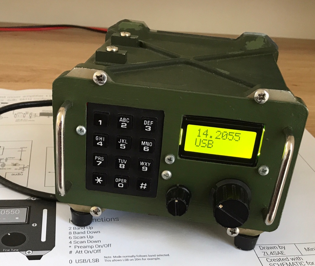
The receiver was constructed on a single PCB using a mixture of techniques. The filters are mounted beneath the board with the remaining circuitry above. The TEENSY 3.2 controller is mounted on the rear of the front panel alongside the keypad and the AD9851 DDS. The controller circuitry is shielded.
The case is an ex-military PRC-351 shell. The handles just look nice.
Tuning is accomplished by ‘scanning’ the band in 1kHz steps, started and stopped from the keypad. The larger of the 2 knobs then allows fine tuning. Pressing the knob selects coarser steps for manual tuning.
The program ‘remembers’ the current frequency when changing bands and on return, that frequency is restored. This function does not survive a power cycle as it is in software and the EEPROM is not used.
Listening on 20m on my 35ft vertical, signals from Europe were heard here in NZ on the first evening of testing. None of these signals were particularly strong, but certainly readable. Maybe a pre-amp would help.
The mini HF Superhet main schematic.

The circuit consists of a Bandpass filter for each band, diode switched by the processor. These are followed by a level 7 diode ring mixer. The common gate FET amplifier is impedance matched to the AM bandwidth roofing filter by the tapping on the tuned winding. The post filter amplifier is a rugged MMIC the GPD202. The SSB filters are relay selected by the TEENSY 3.2 processor on a ‘per band’ basis. The filters were salvaged from the very popular KVN SSB board, available on eBay and a number of other places. See an earlier post for circuit details.
The product detector receives the I/F signal via the noise filter crystals. The output drives the audio preamp, and the single ended output drives the power amplifier. I have made an effort at impedance matching and noise reduction between these 2 stages. The LM380 can deliver 1W into 8 Ohms with some distortion, but is an order of magnitude improvement on the LM386.
The Bandpass Filters

The diode in each of the band-switch circuits serve to isolate the diode switching voltage from the TEENSY. The FET acts as a source follower, providing a few volts to the diodes. As long as the forward voltage drop of the BPF diodes is exceeded the diodes will switch the appropriate filter into circuit. The 220R resistors simply limit the forward current to a safe value. In this case around 10mA.

The Digital VFO and controller

This part of the radio took up most of my time. Between design, build, program and test I spent a few weeks here. The time spent was further extended when I burned out the original TEENSY controller and had to order a replacement. I’m not sure that the level converter is really needed, but once bitten ……
The AD9851 was available after being ‘rescued’ from a previous project. Due to there being insufficient drive for the diode SBL-1 mixer, I used a MMIC to amplify the VFO signal. This is followed by a low pass filter, as the DDS is not know for the cleanest signals. However, in use it performs very well.
The control software
The software was written in the Arduino IDE and downloaded to the processor in the usual way. The main DDS routines appear to be available from many places on the internet and I make no claims for originality here. The number of libraries has been kept to a minimum. Some functions have not been implemented at this time and the software is offered ‘as is’ with plenty of room for improvements and additions.
The .INO sketch is included here as a WORD text file, as WordPress would not allow the .INO file type. Probably for security reasons.
I suggest you cut and paste the text into the Arduino IDE in order to restore the original format.
The button functions that I have used or suggested, appear on the main schematic.
Any further suggestions or improvements are welcome. gw4sae at aol dot com

This is such a cool project! I was researching these very nice KVG TelRad crystal filters and I landed on your site again. The separate offset USB and LSB filters allow you to use a common 9MHz BFO which nestles in quietly next to the SA612. I assume you used the 6kHz AM filter as the roofing filter. Have you been using this Rx recently, the improved band conditions should make it much more fun to use.
73 Paul VK3HN.
LikeLike